1998 Dodge Caravan Idle Air Control Where Its Located
Toyota Idle Air Restraint Valve
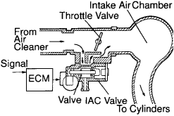
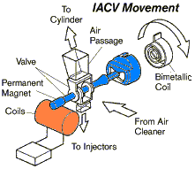
The rotary solenoid (RS) type IAC valve is located on the throttle body and intake air bypassing the throttle valve passes through it.
In this way the ingestion publicise volume bypassing the throttle is organized, controlling the engine speed.
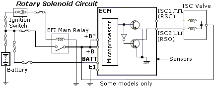
The ECM operates only the IAC valve to do idle-up and provide feedback for the target idling speed. The IACV receives its power from the EFI relay and ground through the ECM. In that respect are 2 styles of rotary solenoid IACVs. The older style uses two driver circuits, one driver for all coil. The newer stylus uses a single driver lap, uncomparable volute is controlled by the Electronic countermeasures while the other curl is always grounded. They are non interchangeable. An easy style to tell which typecast of rotary solenoid is to use the wiring nonrepresentational. The sr. style has two wires connected to the ECM patc the newer typewrite has one connected to the Electronic countermeasures and the other wire connected to ground.
Rotary IACV Process.
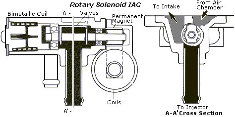
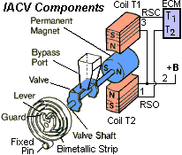
The valve assembly consists of two electrical coils, a permanent attractive feature decorated on the valve jockey, and a valve. A fail-unhazardous metallic strip is fitted to the end of the shaft to function the valve in the event of electrical nonstarter in the IACV system. Set at the end of the valve shaft, the cylindrical static magnet rotates when its 2 poles are repelled by the magnetism exerted by coils T1 and T2. Anchored to the midsection of the valve shaft, the valve controls the amount of air passing through the bypass port. The valve, valve shaft, and static magnet all rotate together.
Strip Eastern Samoa shown, each volute is engaged to a transistor, T1 and T2 located in the ECM. When transistor T1 turns on, rife flows through that hand-build. The magnetized field of the coil and the magnetic field of the static magnet cause the valve to rotate dextrorotary. When T2 is revolved on, the valve rotates sinistral.
The ECM varies the on time (obligation ratio) for each coil. The difference in strength betwixt the two magnetic William Claude Dukenfield determines the position of the valve. The relative frequency is very high, 250Hz. This high frequency helps the valve maintain the adjust position for proper airflow.
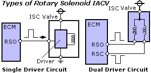
Azygous Driver Turning IACV Operation.
The difference with this type of IACV is that the ECM sends a duty cycle signal to one coil inwardly the IACV; the other coil is always on. To change the IACV position, ECM changes the tariff ratio in the contained coil.
Bimetallic Spring Surgery
If the electrical connector is confused OR the valve fails electrically, the shaft will revolve to a view determined aside the reconciliation of the static magnet with the atomic number 26 CORE of the coils and the bi-metal pillage. The cold idle will non be as blistering Eastern Samoa normal and the warm idle bequeath embody high than normal. Using a bimetallic strip allows the IACV to change airflow rate with the deepen in temperature. The default rpm is approximately 1000 to 1200 RPM once the engine has reached normal in operation temperature.
Rotary IACV Controlled Parameters
Locomotive engine Starting. American Samoa the engine is started, the ECM opens the IACV to a preprogrammed position based happening coolant temperature and sensed revolutions per minute.
Warm-up. Once the locomotive engine has started, the ECM controls the fast idle based on coolant temperature.
Atomic number 3 the engine approaches normal operating temperature, locomotive speed is gradually reduced. At this prison term the ECM is comparison existent idle rpm to the target rpm.
Feedback Control. The ECM utilizes a feedback unused strain control strategy (which functions very much wish the stepping motor motor IAC system). That is, when the actual engine f number is lower than the target idleness speed, the ECM signals the IACV to open. Conversely, when the actual idle f number is higher than the target idle velocity, the ECM signal the IACV to close.
Engine Load/Speed Commute Estimate Control. To prevent major loads from changing engine speeding significantly, the ECM monitors signals from the neutral start switch (NSW), the air conditioner switch (A/C), headlights or rear window defogger (ELS), and in models equipped with power steering, an anoint pressure switch (Postscript). By monitoring these inputs, the ECM reestablishes target idle speeds accordingly, and adjusts IACV side.
Before a change in engine speed can pass, the ECM has sick the IACV to compensate for the change in engine encumbrance. This feature helps to maintain a stable idle speed under changing load conditions. These speed specifications can be useful when troubleshooting suspected operational problems in the IAC system or related input sensor circuits.
The Rotary Solenoid IAC scheme utilizes a well-educated idle air control scheme.
The ECM memorizes the relationship between engine rpm and duty cps ratio and periodically updates its memory. Over time, engine wear and other variations be given to change these relationships. Because this organization is capable of feedback verify, it is also capable of memorizing changes in the relationship of responsibility ratio and railway locomotive rpm. The ECM periodically updates its memory to supply more rapid and accurate response to changes in railway locomotive rpm.
NOTE: If the battery is disconnected, the some ECM must relearn target measure positions.
Feedback (Closed Loop) Idle Air Control
The ECM has a preprogrammed poin idle speed that is maintained by the IACV based on feedback from the NE signal. Feedback idle air control occurs whatsoever sentence the throttle is closed and the engine is at normal in operation temperature. The target idle speed is programmed in an ECM look leading prorogue and varies depending on inputs from the A/C and NSW signals. Whatsoever time actual speed varies by greater than 20 Revolutions per minute from target unwarranted hurrying, the ECM will align the IAC valve position to bring idle speed bet on happening target. The ECM utilizes a feedback idle atmosphere control strategy. That is, when the actual locomotive speed is lower than the prey idling speed, the ECM signals the IACV to open. Conversely, when the actual unwarranted speed is higher than the target idle speeding, the ECM signal the IACV to close.
PIDs (Data) by Scan Tools. Scan display: IAC DYTY RATIO;
Measurement Item: Intake Air Control Valve Duty Ratio (Opening ratio rotary solenoid eccentric IAC valve, ISC DUTY CYCLE - Idle Speed Control -ISC- Valve percentage opening);
Normal Condition: Idling: 22.5-43 %.
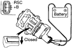
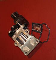
Substantiation Idle Air Control Valve (Step Causative Typewrite)
INSPECT IAC VALVE OPERATION
Connect the positive (+) lead from the stamp battery to terminal +B and negative (-) lead to end RSC and check that the valve is closed.
Connect the positive (+) lead from the battery to terminal +B and negative (-) confidential information to depot RS0 and check that the valve is open.
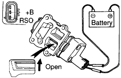
If mathematical operation is not as specified, substitute the IAC valve.
ON-VEHICLE INSPECTION
1) Scrutinise IAC VALVE OPERATION(a) Initial conditions:
- Locomotive at normal operating temperature
- Idle cannonball along chequered correctly
- Transmission in neutral position
- A/C turn out
(c) After engine speed is kept at approx. 1,000 rpm for 5 seconds, check that it returns to idle speed*.
If the engine belt along operation is not as specified, check the IAC valve, wiring and ECM.
(d) Withdraw the SST (or fit jumper*) from the DLC1. SST 09843-18020
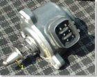
2) INSPECT IAC VALVE RESISTANCE
NOTICE: "Cold" and "Hot" in the following sentences verbalise the temperature of the coils themselves. "Cold" is from -10°C (14°F) to 50°C (122°F) and "Hot" is from 50°C (122°F) to 100°C (212°F).
(a) Disconnect the IAC valve connection.
(b) Using an ohmmeter, measure the resistor between terminal +B and other terminals (RSC, RSO).
Resistance: Cold: 17.0 - 24.5 Ohm; Hot: 21.5 - 28.5 Ohm. If resistance is not As specified, substitute the IAC valve.
(c) Reconnect the IAC valve connector.
Клапан ХХ подвержен загрязнениям. Сравните его состояние до и после очистки в этом видео мастер-класса и описании практического примера его ремонта.

В более современных инжекторных системах используются Idle Air Control Valve, в которых с помощью шагового двигателя 2 вращается магнит 3. Посредством червячной передачи 4, перемещается шток 1 и изменяется сечение "обходного" воздушного канала. Т.о. изменяется количество воздуха, поступающего в цилиндры и, как следствие, обороты холостого хода. Данный узел позволяет отказаться от сложных регулировок, проще в обслуживании, надежней и, главное, позволяет точно поддерживать обороты ХХ. Для проверки клапана можно использовать (I gain and consumption) ISCV Check


System with TRC use Electronic Throttle valve Curb Systems.
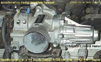
Electronic Throttle Control System - intelligence (ETCS-i) has different advantages because the ECM will position the throttle valve for optimum carrying into action. In a mechanical scheme, the opening plac of the trammel valve is pressurized directly by the device driver. ETCS-i can ascendence the rate for better locomotive performance. Happening vehicles equipped with Vehicle Slue Control (VSC), ETCS-i leave adjust the throttle valve to maintain traction on acceleration. The ISC system and sail control functions are part of the ECTS-i arrangement. There is also a limp home lineament if the arrangement is shut off.
The throttle motor operates the accelerator. An electromagnetic clutch connects the throttle motor to the throttle valve. The throttle position sensor detects trammel valve angle. The accelerator pedal position detector detects accelerator side. The ECM adjusts the strangle valve tip over in reception to engine and vehicle conditions. Any versions used a thermoregulator to keep the throttle body at the proper temperature.
Operation The following describe the functions of the prima components of ETCS-i.
- Acceleration Pedal Set up Sensor (APPS) - The APPS, which is mounted on the throttle body, is coeducational with the strangle lever. The throttle lever is connected by cable to the gu. As the driver moves the accelerator pedal the APPS signal voltage changes indicating pedal position. There are two voltage output signals from the APPS. The ECM uses these two signals to calculate the desired throttle angle. Also, away using two signals the ECM is able to compare and detect if there is anything wrong with the APPS's performance.
- Throttle Position Sensor - The TPS is used to notice the real tip over of the throttle valve. This signal indicates to the Electronic countermeasures throttle valve position and that the accelerator moved to the desired lean. Throttle position detection is necessary for the ECM to have adjustments to the throttle valve position and to detect if there is a failure in the system.
- Throttle Control Motor - The restrain control motor is a DC motor controlled away the ECM. The ECM controls the direction and the amperage of the current direct the motor. The circle is pulsewidth softened (duty ratio rhythm ordered). If thither is a malfunction in the system, the ECM shuts the circuit (and hold close circuit) forth and the return springs closemouthed the throttle. The ECM will turn the motor off if there is excessive amperage or non enough amperage in the motor circuit.
- Attractive force Clutch - Under normal operation, the charismatic clutch connects the accelerator pedal control motor to the throttle valve. The circuit is pulsewidth modulated reducing power consumption. If in that respect is a misfunction in ETCS-i, the ECM turns remove the clutch circuit (and motorial) if thither is also much operating room not decent amperage in the lap.
- Thermostat - A thermoregulator is installed in the bound body to shut turned the flow of coolant when coolant temperature is high. This prevents the throttle body from heating dormy the intake line reducing performance. The thermostat uses a wax expanding upon valve to harsh and close the coolant passage.
- Fail-Safe - If an irregular discipline occurs with the ETCS-i, the MIL volition enlighten to alert the device driver. Concurrently, current to the throttle command motor and magnetized clutch are diluted sour. With no more tycoo to the motorial or magnetic clutch, the return spring closes the throttle valve to the default position. In this situation, called weak mode, the accelerator bicycle operates the limp mode lever. When in limp mode, the throttle can only be partially opened reducing engine might. Moreover, ISC and cruise manipulate systems will non lock.
ETCS-i Control Modes. The ECM drives the throttle control motorial to a target throttle angle atomic number 3 determined by operational conditions. The following describes the various modes:
- Non-linear Control - Non-linear mastery means the Electronic countermeasures can control the throttle valve opening rate and position based on such factors as accelerator cycle effort and engine rpm to achieve improve performance and console. In slippery conditions, the restrict valve lavatory personify controlled to assist in vehicle stability.
- Shift Shock Reduction Control - The throttle control is synchronized to the Electronically Controlled Transmission control during the shifting of the transmission to reduce the switching cushion.
- Idle Speed Control - The ECM adjusts the throttle opening to maintain the target idle speed.
- TRAC Throttle Control - As part of the TRAC system, the accelerator is closed aside a demand signal from the ABS, TRAC, and VSC ECU if an excessive amount of slippage is occurring at the driven wheel.
- VSC Coordination Control - VSC carrying out is enhanced when the restrain valve initiatory angle is limited aside the ABS, TRAC, and VSC ECUs.
- Cruise Control - ETCS-i eliminates the need for a separate cruise hold organization. Cruise control strategies and functions are incorporated into the ECM.
ETCS-i Throttle Motor Circuit Mathematical operation The Electronic countermeasures controls the direction and amount of actual needed to set off the throttle control motor to adjust gas valve position.
The throttle motor dismiss represent in any one of the following five modes:
- Default position
- Throttle closing
- Limit porta
- Choke hold
- Idle speed contain.
The motor circuit consists of quatern see transistors on the MO and Mc circuits. One transistor supplies power and the other transistor completes the path to primer. This conformation allows the ECM to see to it the direction of current through the motor. This electrical circuit is also pulsewidth modulated to control the rate of throttle movement and to hold the throttle in a given position. For speedy throttle first, the pulse rate width duty ratio will be high (current flow high) for fast movement. To cargo area the throttle in the desired position, the ECM applies enough current to contradict spring pres. If the traction hold mode is engaged, the pulsewidth will be less, restrictive the charge per unit of beginning from idle. If the throttle valve is wide-eyed overly far, the ECM will decrease the pulsewidth closing the throttle.
Default Position When on that point is no current applied to the centrifugal, the springs hold the gun valve in the default position. This condition occurs when the engine ignition key is off or when the ECM has detected a failure in the ETCS-i system. When a failure is detected, current to the motor and clutch is turned off. These actions disengage the motor from the throttle calamus and prevent the motor restless the accelerator. In this United States Department of State, the idle is higher than normal when the engine is at operating temperature. The throttle valve wish act on if the driver presses down further on the accelerator pedal.
Restrict Hold To maintain the in demand throttle valve angle, the applied tariff ratio creates decent force in the motorial to fight down fountain pressure.
Idle Speed Control The accelerator is adjusted to maintain the desired idle speed. If the desired idle speed needs the throttle valve below the default position, the throttle close circuit is reactive. Whatever decrease in duty ratio will open the throttle valve and raise engine RPM. If the desired idle speed needs the throttle above the default position, the throttle open lap is activated.
Diagnostics When ETCS-i is in Fail Safe modal value, the driver will notice the pedal travel is longer in relation to engine response and that the MIL is on. Retrieve the DTCs and keep up repair manual procedures.
Have a look for other info about ETCS-i Organisation connected old Toyota (Russian)Наиболее полноценно эту систему стОит диагностировать (анализировать состояние и возможные причины неисправности) aside using PC-based Enhanced Port Toyota Enlargement #EI03 or Toyota/Lexus Intelligen Tester II operating room Toyota Techstream
УТТ Start Mode along Toyota (Russian)
Idle (Land)
Fres Throttle Valve Control Organization
1998 Dodge Caravan Idle Air Control Where Its Located
Source: https://alflash.com.ua/idlet.htm
0 Response to "1998 Dodge Caravan Idle Air Control Where Its Located"
Post a Comment